Saturday, October 22, 2011

Physics Form 4: Chapter 5 - Concave Mirror Ray Diagrams


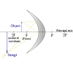
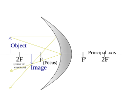
Ray diagrams are constructed by taking the path of three distinct rays from a point on the object:

X) a ray parallel to the principal axis reflected through F (the principal focus)
Y) a ray passing through C which is then reflected back along its original path
Z) a ray passing through F, which is then reflected parallel to the principal axis

Click on the diagram below to play!

--------------------------------------------------------------------------------------------------
Object's position (S),
focal point (F)
Image Diagram
S < F
(Object between focal point and mirror)
  • Virtual
  • Upright
  • Magnified (larger)
Concavemirror raydiagram F.svg
S = F
(Object at focal point)
  • Reflected rays are parallel and never meet, so no image is formed.
  • In the limit where S approaches F, the image distance approaches infinity, and the image can be either real or virtual and either upright or inverted depending on whether S approaches F from above or below.
Concavemirror raydiagram FE.svg
F < S < 2F
(Object between focus and centre of curvature)
  • Real
  • Inverted (vertically)
  • Magnified (larger)
Concavemirror raydiagram 2FE.svg
S = 2F
(Object at centre of curvature)
  • Real
  • Inverted (vertically)
  • Same size
  • Image formed at centre of curvature
Image-Concavemirror raydiagram 2F F.svg
S > 2F
(Object beyond centre of curvature)
  • Real
  • Inverted (vertically)
  • Reduced (diminished/smaller)
  • As the distance of the object increases, the image asymptotically approaches the focal point
  • In the limit where S approaches infinity, the image size approaches zero as the image approaches F
Concavemirror raydiagram 2F.svg
--------------------------------------------------------------------------------------------------

1 comment:

Anonymous said...

Thank you for the notes, teacher! -NIMD